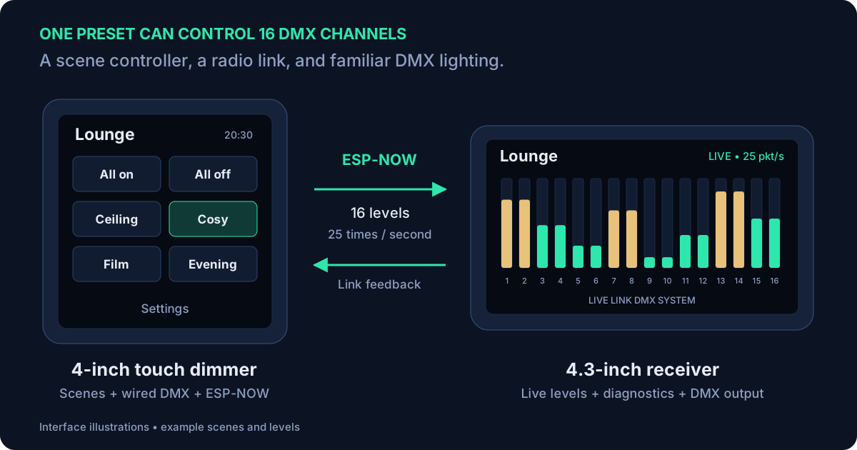
Select a diagram to open its full-size version.
Simple control of many lighting channels
This project started because in rooms such as my living room, there are many different lights: ceiling lights, wall lights, downlights and table lighting that I might want in different combinations. A row of dimmer knobs works, but it is isn't obvious to somebody walking into the room which dimmer knob or switch does what. Often the 'big light' just gets left on at full brightness, which is not particularly flattering light and is not relaxing.
A touchscreen with a few named scenes makes that much easier. Press a button for the lighting you want, or hold it to change the levels behind that scene. The everyday interaction can stay simple even when the wiring and the lighting hardware behind it are more involved.
The controller primarily connects to my own smart-home lighting boards. Those grew out of an earlier series of projects: a main controller with interchangeable modules for trailing-edge AC dimming, low-voltage LED control and relay switching. The touchscreen supplies the requested levels; those boards do the work of controlling the loads. Video #230 gives an overview of those boards and their installation.
I chose DMX for its simplicity and compatibility with a wide range of luminaires. It provides a straightforward way to pass level values to my own boards and to other suitable DMX lighting. The panels in my installation are powered from 24 V DC supplies where needed, and the lighting is a mixture of mains, 24V or MQTT/WiFi/Zigbee controlled smart lamps.
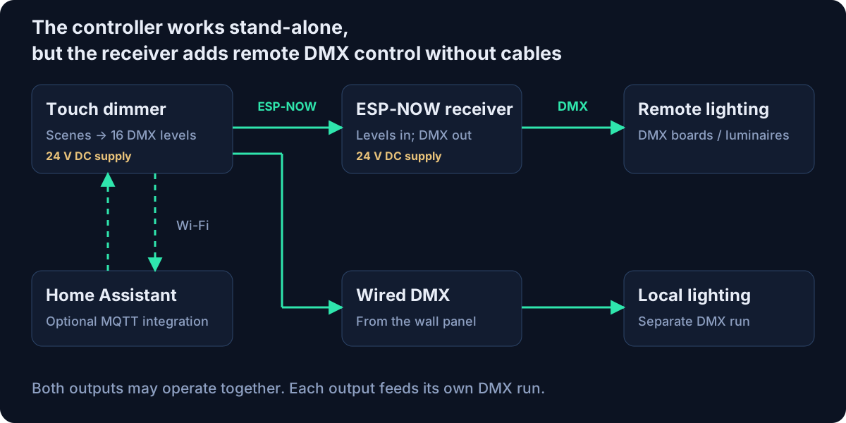
The next problem was the cable. In all rooms I can supply power to the wall panel, but adding a wired DMX connection in certain rooms would mean chasing out the wall again. The wireless extension lets the controller stay at the wall while a separate receiver produces DMX near the lighting hardware. The intended receiver location for one particular room was up in the loft.
The hardware already has the useful interfaces.
The wall controller uses the Waveshare ESP32-S3-Touch-LCD-4: a 4-inch, 480 × 480 touchscreen with an ESP32-S3 and an RS-485 interface. Its size makes it a useful starting point for a wall control. I designed a bezel that mounts it onto a standard UK single-gang back box, covered in video #360.
The receiver uses the ESP32-S3-Touch-LCD-4.3B-BOX, with an 800 × 480 capacitive touchscreen and a ready-made enclosure. Its onboard RS-485 interface means it can generate the wired DMX output without adding a separate transceiver board. Waveshare lists a 7–36 V DC input, so my 24 V supplies are a convenient fit. It also includes CAN, I²C, digital I/O, a microSD slot and battery support, although this project mainly uses power, the display, touch and RS-485. Waveshare’s hardware reference describes those interfaces.
| Role | Display | Firmware folder |
|---|---|---|
| Wall controller | 4-inch square 480 × 480 | TouchDimmer_waveshare480480_Wireless |
| Wireless receiver | 4.3-inch landscape 800 × 480 | WirelessDMX_Receiver_Waveshare43B |
A receiver does not need a large screen just to reproduce DMX values. But these low cost display modules allow for some very useful remote diagnostics: channel levels, signal strength, packet rate and output settings. It also gives me local controls when I am near the receiver doing testing rather than the wall panel.
SquareLine provided the initial GUI baseline.
I used SquareLine Studio for the initial GUI design. The generated code was also a useful baseline for understanding how to create GUI elements: buttons, labels, sliders and screens. That gave me a working starting point to adapt as the project developed.
LVGL is the graphics library underneath the interface. It creates and draws those objects, handles touch events and provides the screen system. The application code gives the controls their meaning: recalling a scene, changing a level, saving a name or pairing a receiver.
In the current controller code, the original SquareLine-generated UI is kept separate from the application handlers and the newer screens written in C++. The application attaches its handlers after the UI has been created. That separation matters: a button can still navigate between screens while doing none of the actual saving or lighting control if the application callback is missing.
The receiver has its own LVGL interface, built around the wider display. Waveshare’s display examples provided the hardware starting point; simple labels, buttons and a changing bar graph established the basics before I expanded the design into a 16-channel monitor. The final screen takes some inspiration from lighting desks, with a clear view of all the levels at once.
Scenes first, DMX underneath.
The controller provides six scenes, each holding a set of levels for six logical lighting groups. A short press recalls a scene. A long press opens its preset editor, where the levels can be adjusted and saved or cancelled. Scene names and lighting-group names are configurable, so the interface can describe the room rather than a list of anonymous channel numbers.
Those six groups are mapped onto 16 DMX slots. A group can drive more than one slot, which is useful when several outputs should follow the same room control. For example, two separate dimmer outputs could both follow “Wall lights”. That is a configurable mapping, not a requirement to wire the room in a particular way.
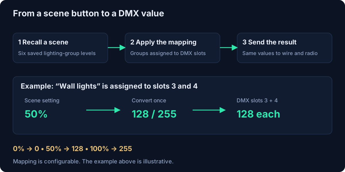
Changing scenes uses a two-second fade. As it progresses, the controller updates the lighting levels, applies the slot assignments and converts percentages to the DMX range of 0–255. The conversion is performed once: 0% becomes 0, 50% becomes 128 and 100% becomes 255.
A dedicated output task takes a snapshot of those 16 values every 40 ms, giving a nominal 25 updates per second. It drives the wired output and, when enabled and paired, sends the wireless packet as well. Keeping that repeated output separate from screen and network servicing helps preserve its cadence while other work is happening.
The saved scenes and assignments are retained in non-volatile storage. Basic scene control and the wired DMX output operate locally; Home Assistant is not needed for pressing a scene button and changing the lights.
Adding ESP-NOW to the existing level stream.
The first radio experiment in the video was deliberately small: send a changing value from one display and show it on the other. That prototype used broadcast packets, a recognisable marker and a counter, with an update every 200 ms. It established that the two displays could exchange data before I connected it to the full lighting application.
The current implementation sends all 16 DMX levels, uses a saved pairing and returns acknowledgements. It is built on Espressif’s ESP-NOW protocol, which allows short messages to pass directly between devices using the Wi-Fi radio without establishing a normal access-point connection between them.
In practice, I can leave Wi-Fi enabled on the wall controller for MQTT and web access while using ESP-NOW for the lighting link. Both share the radio channel. When the controller is connected to an access point, the receiver needs to find that same channel.
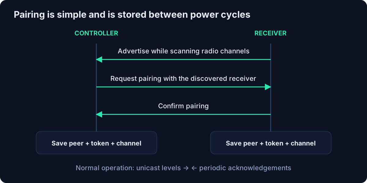
Pairing starts on the receiver’s Link page, then on the controller under Settings → DMX Settings. The receiver scans radio channels and advertises its presence. The controller requests a pairing, the receiver confirms it, and both save the peer details, link token and channel. The receiver has a three-minute pairing window to allow time to get between the two units.
One receiver is paired to a controller at a time. After a restart, the saved link is restored; if the access point changes channel, the receiver can scan again to find the controller. Wireless output can be disabled without forgetting the pairing. Forgetting a peer clears the saved association and also notifies the other end.
The radio transport is specific to this project, so the wireless endpoints need compatible firmware. Compatibility with other luminaires is provided by the wired DMX output at either end.
Sixteen levels in a 36-byte packet.
The wireless link carries the current level values, rather than transmitting the timed electrical DMX waveform. Each normal levels message contains a complete 16-slot snapshot. The receiver then produces its own DMX frames using that data.
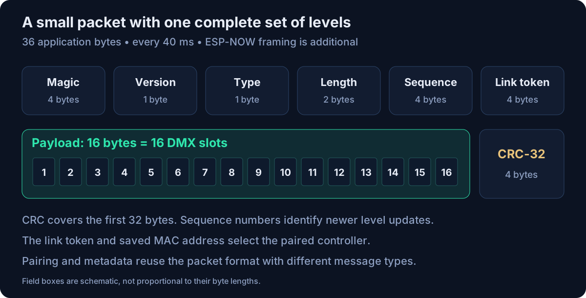
| Field | Bytes | Purpose |
|---|---|---|
| Magic | 4 | WDMX identifies the application format. |
| Version + type | 1 + 1 | Identify the format version and kind of message. |
| Payload length | 2 | States how much of the 16-byte payload is in use. |
| Sequence | 4 | Distinguishes newer level updates and helps estimate missing packets. |
| Link token | 4 | Associates traffic with the saved pairing. |
| Payload | 16 | One byte per DMX slot in a levels message. |
| CRC-32 | 4 | Checks the preceding 32 application bytes. |
The receiver checks the packet size, marker, version, payload bound and checksum before handing data to the application. It then checks that the sender’s MAC address and token match the saved link. These checks reject malformed or unrelated traffic; the current firmware does not enable ESP-NOW encryption, so the token and checksum are not cryptographic security.
The controller sends levels at 25 packets per second. The receiver acknowledges every fifth accepted levels packet, returning the sequence and received signal strength. This gives the controller useful evidence that its receiver is still hearing it. Lost level packets are not individually resent by the application: the next update contains the full current state.
The same packet layout also carries pairing messages, the room title and channel labels. A capability exchange lets the controller find out whether the receiver supports labels. Those messages have their own sequence counter so a label update does not look like a missing lighting packet in the diagnostics.
A receiver with easy diagnostics.
The receiver’s main screen shows 16 vertical meters. Their heights and colours make it easy to spot which outputs are active, while the numeric readout can show percentages or the underlying 0–255 values. Room and slot names received from the controller make the display easier to relate to the installation.
The Link page adds RSSI, packets per second, the sender’s MAC address, the radio channel and a signal-strength history. Packet counters help distinguish malformed packets, missed sequence numbers and duplicates. The DMX page holds output settings and test controls; the System page provides firmware and diagnostic information.
Internally, the receiver keeps the newly received target levels separate from the levels it is actually outputting. The DMX transmitter and the meters read the actual output state, so fades and local testing are reflected on the display. Radio callbacks perform short checks and copy incoming data; display drawing and saved-setting changes happen outside those callbacks.
There are two output modes. RAW applies the latest values directly. SMOOTH ramps toward each changed target over a configurable time, with a default of 40 ms. This helps make transitions less abrupt when incoming updates are uneven. Repeated identical packets do not restart the ramp, so it can reach the requested endpoint.
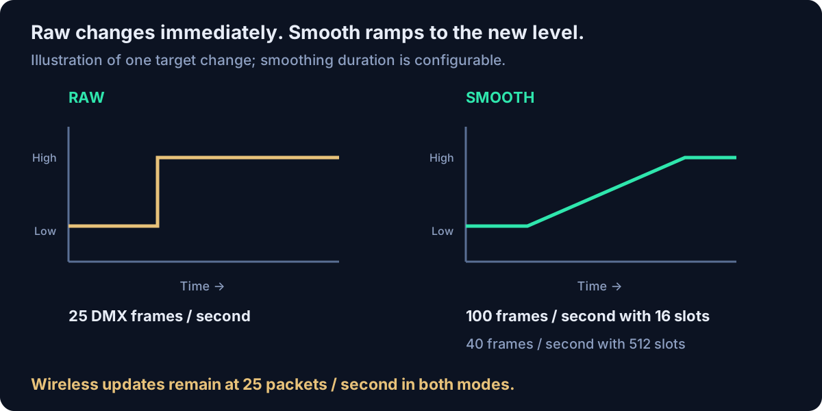
The RS-485 output uses 250,000 baud, eight data bits, no parity and two stop bits. The firmware adds the DMX break, mark-after-break and zero start code, followed by the slots. It can send either 16 slots or a full 512-slot frame. Full mode still carries only 16 wireless-controlled levels; slots 17–512 are filled with zero.
| Mode | 16 slots | 512 slots |
|---|---|---|
| RAW | 25 Hz | 25 Hz |
| SMOOTH | 100 Hz | 40 Hz |
A full frame takes longer to transmit, which is why smooth mode uses a lower rate at 512 slots. These are output schedules; the incoming wireless stream remains at 25 Hz.
Hold the last levels, then fade to blackout.
A wireless link needs a defined response when updates stop. With the default settings, the receiver marks the link as lost after 1.5 seconds without a valid levels packet. It keeps the last output levels until the packet age reaches ten seconds, then fades to zero over two seconds. The ten-second hold is measured from the last packet, not from the later “signal lost” indication.
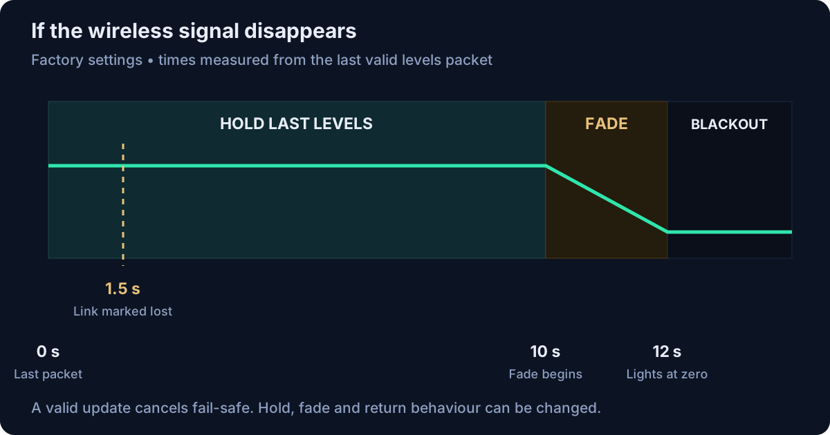
The settings allow different behaviour, including holding indefinitely. A valid update cancels fail-safe and returns control to the wireless source, with the configured return time; the default return is immediate.
Local Test mode is useful when checking the receiver end of an installation. After deliberately enabling it, I can select a channel and adjust its output from the receiver’s touchscreen. Radio reception and link statistics continue in the background, while the local controls temporarily own the output.
Leaving Test mode returns to the latest valid wireless state, or the applicable fail-safe state if the link is unavailable. It also exits after five minutes without a Test touch. Temporary test levels are not saved across restarts.
Home Assistant can join in through MQTT.
Local scene control is the starting point, but Wi-Fi and MQTT allow the controller to participate in the wider smart home. It publishes scene state and accepts commands, so an automation can select a scene using the same activation path as a press on the display.
The default state topic is dimmer-system/scene, and commands go to dimmer-system/scene/set. Scene numbers run from 0 to 5. For example, this Home Assistant action selects the fourth saved scene:
action: mqtt.publish
data:
  topic: dimmer-system/scene/set
  payload: '{"scene":3}'
  qos: 0
  retain: false
Live-level commands can set the six current percentages without overwriting a preset. The following JSON goes to the same command topic and uses the normal scene fade:
{"mode":"levels","brightness":[20,40,60,0,0,10]}The expanded configuration interface uses /config/set below the configured base topic. It can update scene names and levels, lighting-group names and DMX assignments, the room name, network settings, wireless enablement, timezone and backlight levels. Results are published on /config/result, with retained configuration state under /config/state/….
Each controller has its own MQTT client ID. Give rooms distinct base topics when they should be controlled independently. Scene and configuration commands should be non-retained so they are not replayed when a controller reconnects. The firmware’s MQTT connection is unencrypted; broker access control belongs on a trusted local network.
Set up the room from a browser.
The current controller also provides a local web administration page once it is connected to Wi-Fi. The touchscreen’s Settings → System Information → Web Admin page shows its address and per-unit password; the username is admin.
From there, I can edit the room name, scenes, lighting-group names and DMX mapping, along with Wi-Fi, MQTT, timezone and display settings. The browser uses the same validation and saved settings as the touchscreen. Password fields preserve existing secrets when left blank rather than exposing the stored value.
The display includes a network-synchronised clock and configurable active and idle backlight levels. On board revisions with supported backlight control, the factory behaviour waits ten seconds after the last touch, then fades from 100% to 50% over ten seconds. Touching the screen restores the active brightness. Settings are kept in non-volatile storage.
Browser-based firmware updates are useful because the wall bezel makes regular access to the USB connector inconvenient. An update must first be enabled on the touchscreen, opening a ten-minute upload window. The web updater writes the correct application image to the inactive OTA partition and then restarts the controller.
During an update, the controller shows a static update screen and pauses its wired and wireless output. That makes receiver fail-safe settings relevant during maintenance too. Pairing, forgetting a receiver, enabling updates and factory reset remain deliberate touchscreen operations. Restart preserves settings; factory reset clears them.
These web functions belong to the wall controller. The 4.3-inch receiver is configured through its own touchscreen; it does not need to join the home Wi-Fi network.
From matching bars to a real light.
Seeing the right values on the receiver screen was the first check. The next was to look at the actual DMX output with the oscilloscope supplied by eVision Instruments. In video #374 I used serial decoding to compare the transmitted values with the display, changed between short and full frames, and checked the effect of changing the output rate.
I then connected a DMX light, tried the receiver’s local test controls and adjusted levels remotely. The dimming looked smooth in that demonstration. I also reported a working link over roughly 15 metres in my house, with brick walls between the units. That is a result from this installation, rather than a range specification for every building.
At the end of filming I planned to leave the system running to check for problems over time. Since then, everything has been working well. The original wired controller had already been in use for more than a year when I made this wireless update.
The receiver uses the board’s onboard, automatic-direction RS-485 interface, which is not galvanically isolated. Its output has been checked on the bench and used with fixtures; those results do not establish compatibility with every DMX device or cable installation.
The useful outcome is straightforward: I have the same scene-based control at the wall, and I can put the DMX connection where it is needed. The receiver screen also makes that invisible wireless link much easier to understand when setting up or diagnosing the lighting.
Firmware details and earlier work.
This article covers the current implementation as well as the development shown in #374; the early broadcast demonstration is one step in that history.
The touchscreen project
The earlier smart-home lighting boards 7 videos
JLCPCB — Sponsor of video #374.
Waveshare — Supplied the displays for the project.
eVision Instruments — Supplied the oscilloscope used in the video.