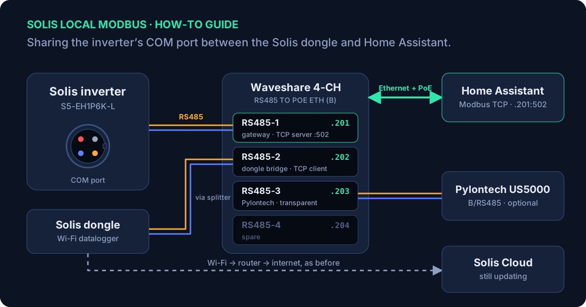
Select a diagram to open its full-size version.
Why the COM port needs a gateway
Solis hybrid inverters have a single 4-pin COM port, and that’s where the Solis datalogger dongle plugs in. The dongle acts as a Modbus RTU master: it regularly polls the inverter over RS485 and uploads the readings to Solis Cloud. That works well, but it leaves no obvious way to read the same data locally for Home Assistant, battery automation or your own logging.
The difficulty is that Modbus RTU only allows one master on an RS485 bus. If you connect a second adapter to the same pair, sooner or later both will transmit at the same time. The messages collide, replies are corrupted or go to the wrong device, and both ends start seeing timeouts.
The common workarounds all have a downside. Unplugging the dongle gives you clean local access, but you lose Solis Cloud, the app and your installer’s remote access. Some dataloggers can provide Modbus TCP themselves, but not reliably: the S2-WL-ST only accepts one TCP connection and can drop off the cloud while an integration is connected, and the DLS-W and S3-WIFI-ST don’t offer Modbus TCP at all.1
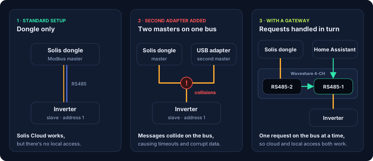
This guide takes the gateway approach. It’s based on alienatedsec’s solis-ha-modbus-cloud design, which uses two single-channel Waveshare RS485-to-Ethernet converters.1 Here, the same idea is built on a single Waveshare 4-CH RS485 TO POE ETH (B), which has four independent, isolated RS485 channels, each with its own IP address, behind one PoE network port.2 That leaves one channel free for a Pylontech battery stack, and another spare.
How the two-channel setup works
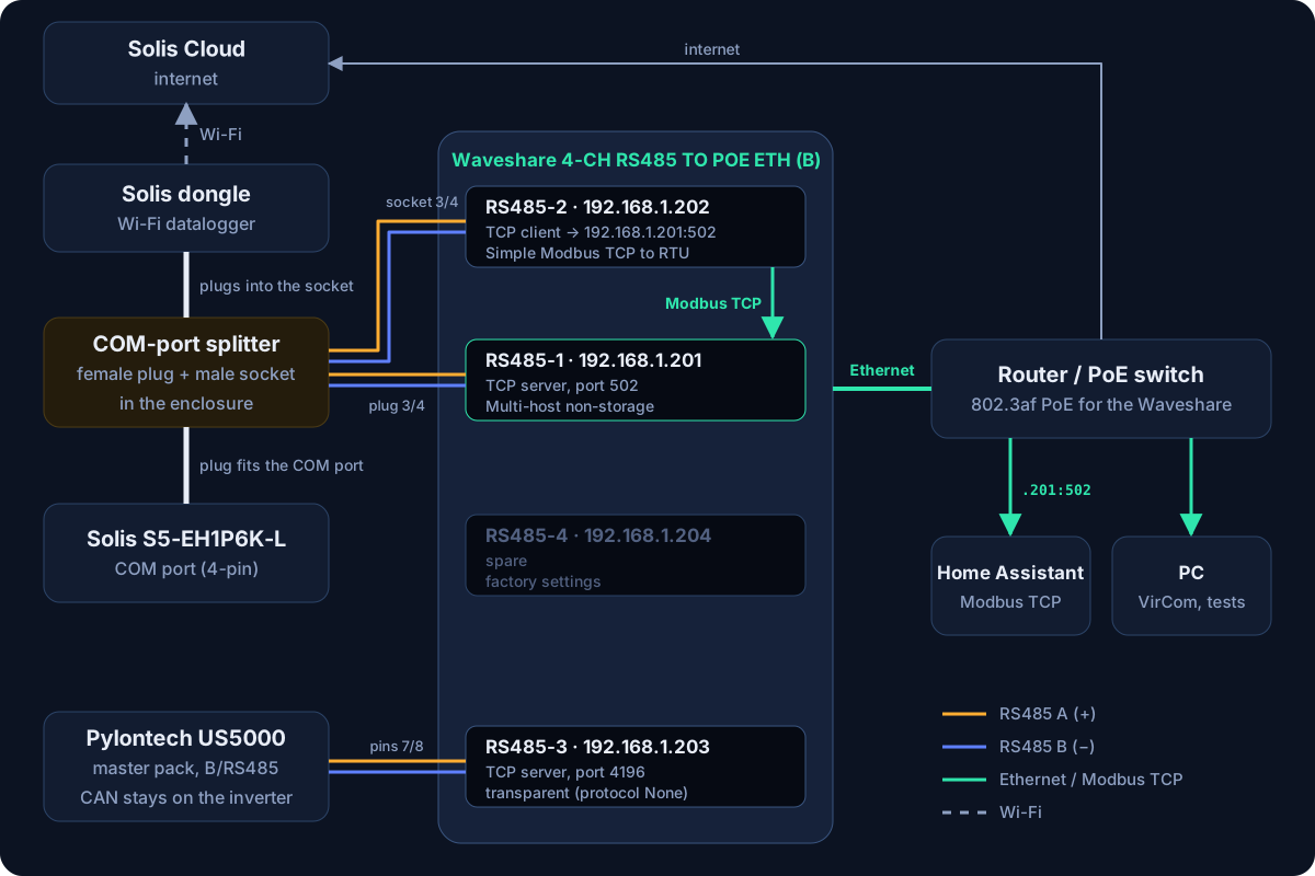
A small splitter divides the COM connection in two, so the inverter and the dongle each have their own RS485 pair, connected to separate channels on the Waveshare gateway. Each channel has its own job:
- RS485-1 (192.168.1.201) is wired to the inverter and acts as a Modbus TCP server on port 502. In multi-host mode it accepts connections from several TCP clients and passes their requests to the inverter one at a time.
- RS485-2 (192.168.1.202) is wired to the dongle. It converts the dongle’s RTU requests into Modbus TCP, forwards them to RS485-1 and passes the replies back.
- RS485-3 (192.168.1.203) is an optional, transparent link to the Pylontech battery’s RS485 port. The battery doesn’t use Modbus, so the gateway simply passes the data through unchanged.
As far as the dongle is concerned, it’s still talking directly to the inverter, so Solis Cloud, the app and remote control all carry on working. Home Assistant connects to 192.168.1.201 on port 502, just like any other Modbus TCP device.
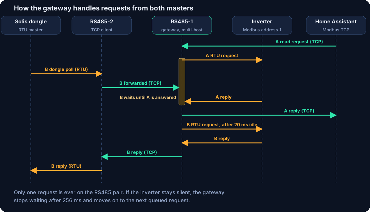
How requests are kept apart
In multi-host mode, the gateway only ever has one request outstanding on the RS485 bus. If a second request arrives, from either the dongle or Home Assistant, it’s held until the first reply comes back. Two settings control the timing: the gateway waits up to 256 ms for a reply before giving up, and only transmits once the bus has been idle for 20 ms. Both values come from alienatedsec’s configuration.
There’s also a useful side effect. Because the two halves are only linked over TCP, they don’t need to run at the same speed. The dongle side has to match the dongle (9600 baud), but the inverter side can be increased later if your inverter supports a faster Modbus speed.
The gateway modes, timings and splitter idea all come from alienatedsec’s solis-ha-modbus-cloud project. This guide adapts them for the 4-channel unit and adds pinouts, channel assignments and test scripts.
What you’ll need
| Item | Purpose | Notes |
|---|---|---|
| Waveshare 4-CH RS485 TO POE ETH (B) | The gateway | Four isolated RS485 channels, powered by PoE (IEEE 802.3af) or 6–45 V DC. The non-PoE version, the 4-CH RS485 TO ETH (B), works in the same way with a DC supply. |
| PoE switch or injector | Power and network over one cable | Must support 802.3af. Alternatively, use a 6–45 V DC supply on the power terminals. |
| Exceedconn EC04681-2023-BF pair | The splitter | A female plug to fit the inverter’s COM port, and a male socket for the dongle to plug into. Both can be wired in the field. |
| Solid-core Cat5e or Cat6 | RS485 and 5 V wiring | Use one twisted pair for each RS485 connection. |
| Enclosure, DIN rail and cable glands | Housing | IP65 if it’s going outdoors. A small consumer-unit box usually includes DIN rail and glands. |
| RJ45 plug and crimp tool | Battery connection (optional) | Only pins 7 and 8 are used, plus pin 6 if you want a ground connection. |
| Multimeter | Checking your work | For continuity checks before power-up, and for checking the 5 V supply before the dongle is reconnected. |
| Windows PC with VirCom | Configuring the gateway | Waveshare’s configuration tool. The multi-host options are in its More Advanced Settings dialog. |
| Python 3 | Running the test scripts | Both scripts only use the standard library. |
Compatible dataloggers
alienatedsec lists the DLS-W, DLS-L, S2-WL-ST and S3-WIFI-ST as working with this setup, with the 4-pin S1-W4G-ST untested. Dataloggers with a USB connector, as used on the S6 range, won’t fit a 4-pin splitter.1
The dongle-side channel has to match the dongle’s serial speed. The S2-WL-ST and S3-WIFI-ST default to 9600 baud, and on a DLS-W the speed can be changed from a hidden page at /config_hide.html.
Connector pinouts
Solis COM port
The COM port is the green 4-pin Exceedconn connector on the underside of the inverter. Solis’s own troubleshooting article lists the pin functions and includes photos of the connector.3
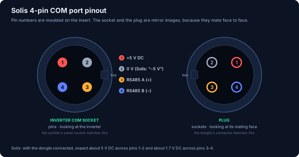
| Pin | Function | Connection in this setup |
|---|---|---|
| 1 | +5 V DC | Passed straight through from plug to socket to power the dongle |
| 2 | 0 V (shown by Solis as −5 V) | Passed straight through from plug to socket |
| 3 | RS485 A (+) | Plug: to RS485-1 A+. Socket: to RS485-2 A+. |
| 4 | RS485 B (−) | Plug: to RS485-1 B−. Socket: to RS485-2 B−. |
Waveshare 4-CH terminals
The gateway has a 6-way terminal block at the Ethernet end for channels 1 and 2, and an 8-way block at the other end for the power input and channels 3 and 4. Each channel has its own A+, B− and signal ground terminals. Using channels 1 and 2 for the splitter keeps both pairs at the same end of the unit.2
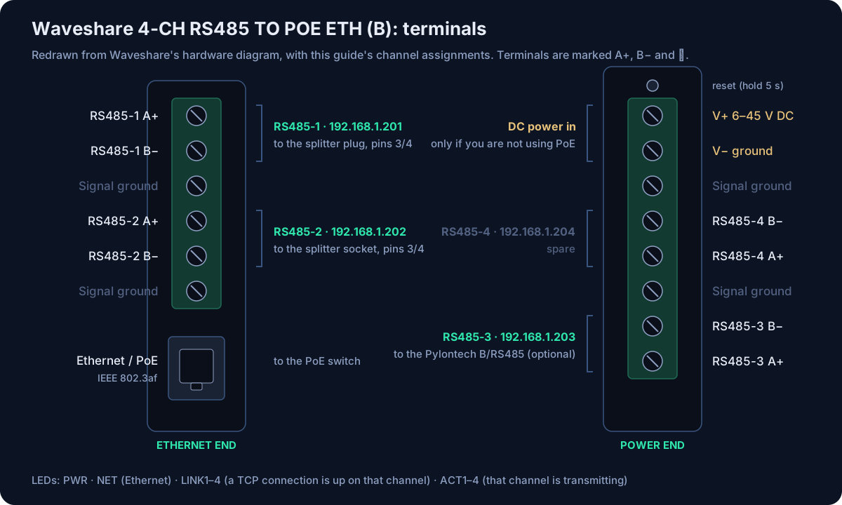
| Channel | IP address | Role | Wired to | Mode |
|---|---|---|---|---|
| RS485-1 | 192.168.1.201 | Inverter gateway | Splitter plug, pins 3/4 | TCP server :502, Modbus TCP, multi-host |
| RS485-2 | 192.168.1.202 | Dongle bridge | Splitter socket, pins 3/4 | TCP client → 192.168.1.201:502 |
| RS485-3 | 192.168.1.203 | Battery (optional) | Pylontech B/RS485, RJ45 pins 7/8 | TCP server :4196, transparent |
| RS485-4 | 192.168.1.204 | Spare | — | Factory settings |
These addresses are examples for a 192.168.1.x network. Any free static addresses will do, but matching each address to its channel number makes the rest of the setup easier to follow. The Pylontech RJ45 pin definitions are in section 09, alongside the battery wiring.
Configuring the Waveshare gateway
It’s easiest to do this on the bench before going anywhere near the inverter, so the installation itself is just a case of plugging things in. Use VirCom for the configuration rather than the built-in web page, as alienatedsec recommends. The multi-host options are in its More Advanced Settings dialog.
Find the four channels in VirCom
Install VirCom from the Waveshare wiki and open Device Management. Each channel shows up as a separate device, named RS485-1 to RS485-4, with its own MAC and IP address. Waveshare’s FAQ shows that the IP addresses aren’t necessarily in channel order, so go by the names.2
Set a static IP address for each channel
Set IP Mode to Static and give RS485-n the address 192.168.1.20n, with a subnet mask of 255.255.255.0 and your router as the gateway. Make sure these addresses are outside your router’s DHCP range. RS485-2 connects to RS485-1 by IP address, so RS485-1’s address must not change.
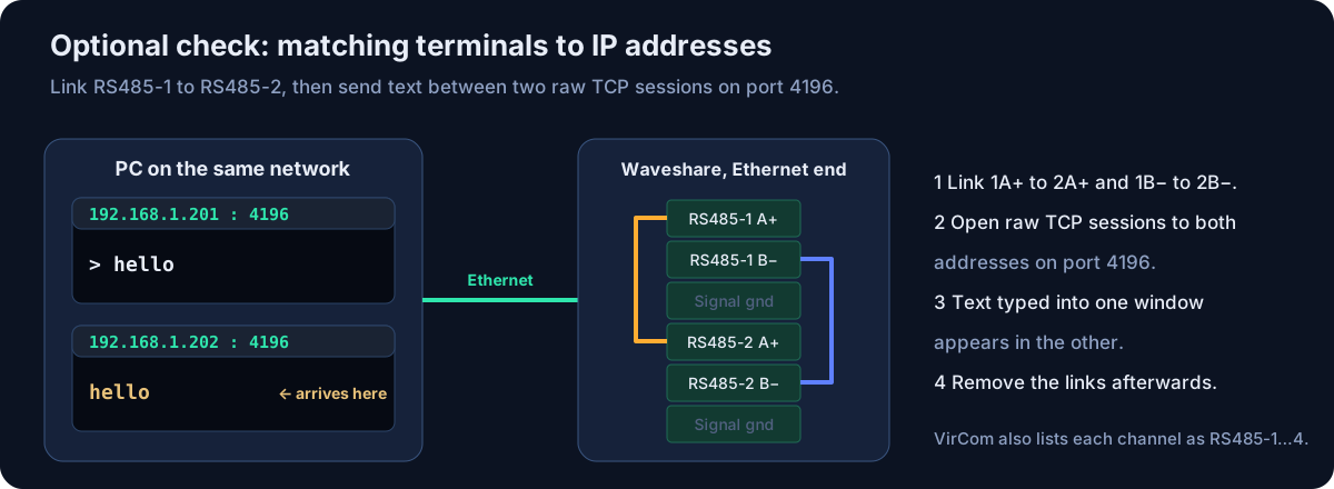
Optional: confirm which terminals belong to which channel
With all channels still on factory settings, link RS485-1 A+ to RS485-2 A+, and B− to B−. Open raw TCP sessions to both addresses on port 4196 using SSCOM, PuTTY in Raw mode or ncat. Anything typed into one session should appear in the other. Remove the links when you’ve finished.
RS485-1 settings (inverter gateway)
Double-click RS485-1, enter the settings below, then click More Advanced Settings… for the multi-host options. When you’re done, click Modify Setting, then Restart Dev.
| Setting | Value |
|---|---|
| Work Mode | TCP Server |
| Port | 502 |
| Transfer Protocol | Modbus_TCP Protocol |
| Baud rate / data / parity / stop | 9600 / 8 / None / 1 (the inverter’s default) |
| Keep Alive, Dest. Mode, Framing | Leave at defaults (60 s, Dynamic, 1300 bytes / 3 ms) |
| Modbus Gateway Type (More Advanced Settings) | Multi-host non-storage type |
| Enable RS485 Multi-Host (More Advanced Settings) | Ticked, with a maximum wait time of 256 ms |
| RS485 bus conflict detection (More Advanced Settings) | Ticked, with a bus idle time of 20 ms |
RS485-2 settings (dongle bridge)
| Setting | Value |
|---|---|
| Work Mode | TCP Client |
| Port (local) | 0 (assigned automatically) |
| Dest. IP / Dest. Port | 192.168.1.201 / 502 |
| Transfer Protocol | Modbus_TCP Protocol |
| Baud rate / data / parity / stop | 9600 / 8 / None / 1 (to match the dongle) |
| Reconnect Time | Leave at default (12 s) |
| Modbus Gateway Type (More Advanced Settings) | Simple Modbus TCP to RTU |
| Enable RS485 Multi-Host (More Advanced Settings) | Unticked (wait time 0) |
| RS485 bus conflict detection (More Advanced Settings) | Unticked |
RS485-3 and RS485-4 settings
| Setting | Value |
|---|---|
| Work Mode / Port | TCP Server / 4196 (factory default) |
| Transfer Protocol | None (data passes straight through) |
| Baud rate / data / parity / stop | 115200 / 8 / None / 1 if DIP switch 1 on the battery is off, or 9600 if it’s on (see section 09) |
| Multi-host, conflict detection | Unticked |
RS485-4 can be left on its factory settings.
Checking the configuration
From a PC on the same network, run the following in PowerShell. It should report TcpTestSucceeded : True.
Test-NetConnection 192.168.1.201 -Port 502If you run the read test at this stage, it should connect and then time out, as nothing is wired up yet.
If you lose track of a channel’s address, holding the reset button for 5 seconds restores the factory settings, including the default address of 192.168.1.254. If the web page stops loading after trying Waveshare’s MQTT or JSON firmware, the web files can be reloaded from the wiki; VirCom continues to work either way.2
Wiring details for the splitter
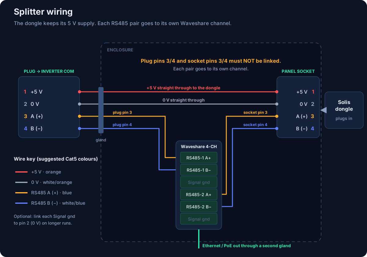
The splitter is the only part you need to wire yourself. A female plug fits the inverter’s COM port, and its 5 V supply is passed straight through to a panel-mounted male socket for the dongle. The two RS485 pairs are not linked through; each one goes to its own Waveshare channel.
Mount the parts
Fit the Waveshare to DIN rail inside the enclosure. Mount the male socket in the side of the enclosure, somewhere the dongle can plug in and still get a good Wi-Fi signal. Bring a short 4-core cable from the female plug in through one cable gland, and the Ethernet cable through another.
Wire the 5 V supply through to the dongle
Connect plug pin 1 to socket pin 1, and plug pin 2 to socket pin 2. These two wires supply all of the dongle’s power, as the Waveshare doesn’t provide any. On a longer cable, double up the conductors for each to reduce the voltage drop.
Wire the inverter-side RS485 pair
Connect plug pin 3 to RS485-1 A+ and plug pin 4 to RS485-1 B−, using one twisted pair.
Wire the dongle-side RS485 pair
Connect socket pin 3 to RS485-2 A+ and socket pin 4 to RS485-2 B−, using a second twisted pair.
Before connecting anything to the inverter, check the following with a meter, with everything unpowered:
- There is continuity between plug pin 1 and socket pin 1, and between plug pin 2 and socket pin 2.
- There is no continuity between plug pins 3/4 and socket pins 3/4. If they’re connected, you’ve put two masters back on the same bus.
- There are no shorts between any two pins on the plug, and pin 1 connects to nothing other than socket pin 1.
- Plug pin 3 connects to RS485-1 A+, and socket pin 3 connects to RS485-2 A+.
Termination resistors aren’t needed. alienatedsec notes that both the inverter and the Waveshare already terminate the bus, so don’t add 120 Ω resistors. Connecting only A and B normally works because the Waveshare channels are isolated, but if you see errors on a longer cable run, connect each channel’s signal ground to pin 2 (0 V) on the same side.1
Installing at the inverter
Record a baseline
Make a note of the dongle model from its label, and check that Solis Cloud is updating normally. Note the time of the last update, so you can confirm afterwards that the dongle is still getting through.
Remove the dongle
Unscrew the dongle from the COM port. The port only carries extra-low voltage (5 V), so the inverter can stay running, although there’ll be a short gap in the cloud data.
Fit the splitter and check the 5 V supply
Plug the splitter’s female plug into the COM port. Using a meter on the panel socket, check for about +5 V on pin 1 relative to pin 2 before you reconnect the dongle.
Reconnect the dongle
Plug the dongle into the panel socket. Its LEDs should come on as they did before.
Power up the Waveshare
Connect its Ethernet port to the PoE switch or injector, or connect a 6–45 V DC supply. The PWR and NET LEDs should light, and LINK2 lights once RS485-2 has connected to RS485-1.
Testing and commissioning
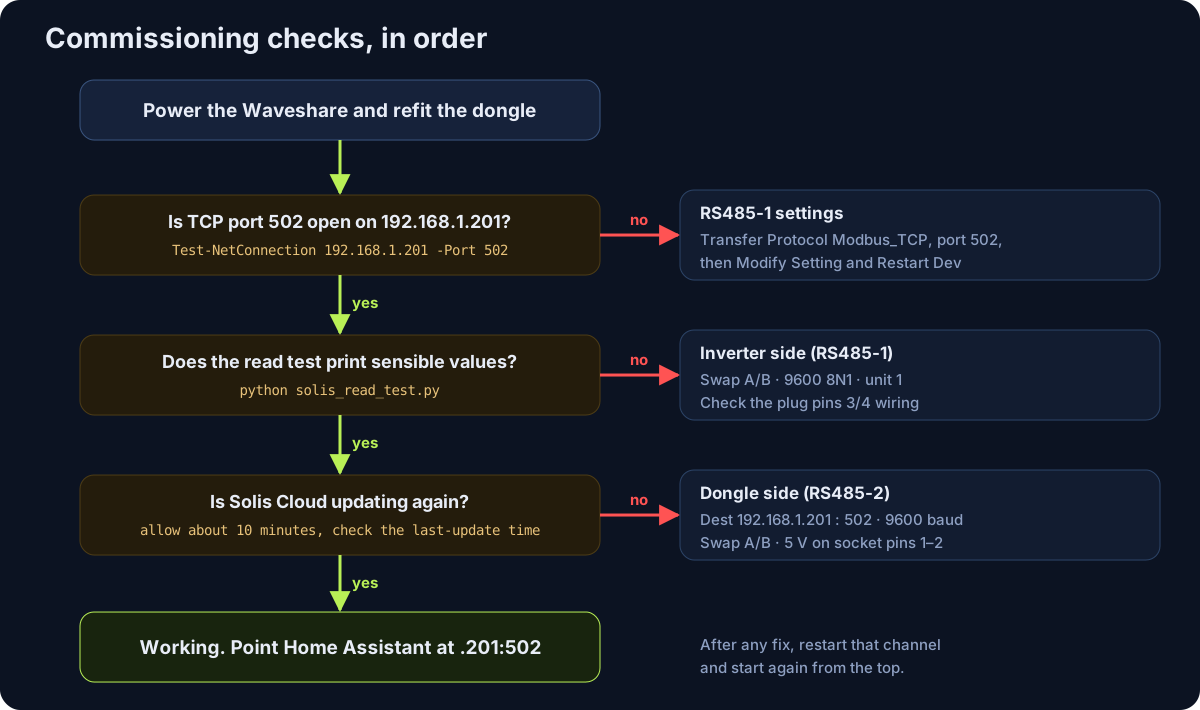
Work through the three checks below in order. If one fails, it points to a specific half of the system, which keeps fault-finding quick.
Reading the inverter directly
solis_read_test.py reads a handful of input registers through the gateway, using only Python’s standard library. It doesn’t write anything to the inverter. Run it from any PC on the network and compare the results with the inverter’s display. The output should look something like this, although your figures will be different:
> python solis_read_test.py 192.168.1.201 502 1
Connected to 192.168.1.201:502, unit 1
Inverter clock   : 2026-10-06 13:45:30
PV power         : 2350 W
Inverter AC power: 1195 W
Inverter temp    : 41.2 C
Battery voltage  : 52.3 V
Battery current  : 22.0 A (charging)
Battery SOC      : 77 %
House load       : 640 W
Battery power    : 1150 W
Running it for a day
Leave it polling every 5 to 15 seconds for a day, and check that Solis Cloud keeps updating throughout. alienatedsec found the setup more reliable with frequent polling, around every 5 seconds, than with long gaps between reads.1
If the read test times out but Solis Cloud is working, try swapping A and B on RS485-1. If Solis Cloud has stopped updating but the read test works, the problem is on the RS485-2 side. Swapping A and B on an RS485 connection won’t cause any damage.
Adding Pylontech battery monitoring (optional)
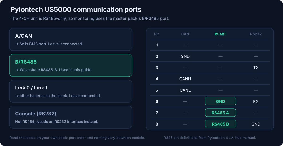
The 4-CH unit only has RS485 channels, so it can’t use the Console port that most Pylontech monitoring projects connect to, because that port is RS232. Use the B/RS485 port on the master battery instead. It uses Pylontech’s own ASCII protocol rather than Modbus, so RS485-3 is set to pass data straight through, and the protocol is handled by software on your network.
Check the DIP switch speed setting
According to python-pylontech, DIP switch 1 sets the RS485 speed: off for 115200 baud, on for 9600.7 Take a photo of the switches before changing anything, as the CAN connection to the Solis depends on them. Restart the battery after any change, and set RS485-3 to the same speed.
Make up the cable
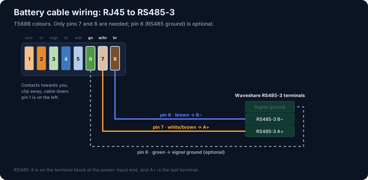
Crimp an RJ45 plug onto a twisted pair, with pin 7 going to RS485-3 A+ and pin 8 to RS485-3 B−. Pin 6 is the RS485 ground and can optionally be connected to the channel’s signal ground.
Run the battery test
pylontech_test.py sends the manufacturer-info and analogue-values commands to a range of addresses and prints the replies. A reply starting with ~20 and showing RTN 00 means it’s working.
If the battery doesn’t respond
Try swapping A and B, then check the baud rate against the DIP switch. If there’s still no response, briefly unplug the CAN cable at a quiet moment and try again. If the battery responds now, you’ve run into the CAN/RS485 conflict. The inverter will raise a BMS communication alarm while CAN is disconnected, so plug it back in straight away.
python pylontech_test.py 192.168.1.203 4196 2 9For ongoing monitoring, python-pylontech can connect to the channel through a socat virtual serial port on Linux. On Windows, VirCom can map RS485-3 to a virtual COM port for Pylontech’s own PC software, which is how alienatedsec monitors their batteries.1,7 If the RS485 port won’t work alongside CAN, the alternative is to use the Console port with an RS232 interface, such as a Waveshare RS232/485/422 TO POE ETH, or an ESP32 with a MAX3232 as used by the ESPHome Pylontech component.9
Connecting Home Assistant
| Integration | Best for | Connection settings |
|---|---|---|
| homeassistant-solax-modbus | The most widely used local integration, with a Solis plugin. Predbat works on top of it. | TCP, host 192.168.1.201, port 502, Modbus address 1, inverter type Solis |
| solis_modbus | A Solis-specific integration that lists the S5-EH1P as supported. | TCP to 192.168.1.201:502, using its Waveshare connection option |
| solis-sensor / solis-cloud-control | Reading and control through Solis Cloud. | Not affected, as they use the cloud, which the dongle still feeds |
- Always connect to 192.168.1.201:502. The 192.168.1.202 channel is reserved for the dongle.
- Only run one local Modbus integration at a time, as two would double the traffic on the bus.
- Set the polling interval to between 5 and 15 seconds.
- Both Solis Cloud and your automations can change settings such as charge times. Decide which one is in charge of each setting, so they don’t keep overriding each other.
- Holding registers (43xxx) contain settings. Reading them is fine, but only write to them when you mean to, and never in a tight loop.
Common problems and fixes
| Symptom | Likely cause | What to do |
|---|---|---|
| Port 502 closed on .201 | Settings weren’t saved, or Transfer Protocol isn’t set to Modbus_TCP | Re-apply the settings in VirCom, then click Modify Setting and Restart Dev. |
| Read test connects but then times out | A and B reversed on RS485-1, wrong baud rate or unit ID, or a wiring fault | Swap A and B on RS485-1, and check the settings are 9600 8N1 with Modbus address 1. |
| Dongle LEDs off | Pins 1 and 2 not passed through, or reversed | Check for about +5 V on socket pin 1 relative to pin 2. |
| Dongle on, but Solis Cloud not updating | RS485-2 wiring, A and B reversed, baud rate mismatch or wrong destination address | Swap A and B on RS485-2. Check the destination is 192.168.1.201:502 and that LINK2 is lit. |
| Intermittent dropouts in Home Assistant | Polling too often, two integrations running, or multi-host not enabled | Poll every 5–15 s, run only one integration, and check both options are ticked on RS485-1. |
| RS485-2 loses its connection after a router change | RS485-1’s address has changed (DHCP) | Use static addresses, and keep .201–.204 outside the DHCP range. |
| No response from the battery | Wrong port, A and B reversed, baud rate doesn’t match DIP switch 1, wrong address range, or a CAN conflict | Work through the steps in section 09. |
| Web page won’t load | MQTT or JSON firmware has replaced the web page | Use VirCom, or reload the web files from the Waveshare wiki. |
| Can’t reach a channel | Address unknown after changing settings | Hold the reset button for 5 seconds to restore the factory address, 192.168.1.254. |
Registers, scripts and related projects
Solis input registers used by the test script
Modbus function 04, unit 1. Register addresses are as used by the homeassistant-solax-modbus Solis plugin, and 32-bit values are sent high word first.10
| Register | Meaning | Type and scale |
|---|---|---|
| 33022–33027 | Inverter clock: year, month, day, hour, minute, second | U16 each |
| 33057–33058 | PV total power | U32, W |
| 33079–33080 | Inverter AC (active) power | S32, W |
| 33093 | Inverter temperature | S16, ×0.1 °C |
| 33133 | Battery voltage | U16, ×0.1 V |
| 33134 | Battery current | S16, ×0.1 A |
| 33135 | Battery current direction (0 = charge, 1 = discharge) | U16 |
| 33139 | Battery state of charge | U16, % |
| 33147 | House load | U16, W |
| 33149–33150 | Battery power | S32, W |
solis_read_test.py Modbus TCP read test · download
"""Read a few Solis hybrid inverter registers through the Waveshare Modbus TCP gateway.

No third-party packages needed (plain sockets, Modbus function 04).

Usage:  python solis_read_test.py [host] [port] [unit]
        defaults: 192.168.1.201 502 1
"""
import socket
import struct
import sys

HOST = sys.argv[1] if len(sys.argv) > 1 else "192.168.1.201"
PORT = int(sys.argv[2]) if len(sys.argv) > 2 else 502
UNIT = int(sys.argv[3]) if len(sys.argv) > 3 else 1


def recv_exact(sock, n):
    buf = b""
    while len(buf) < n:
        chunk = sock.recv(n - len(buf))
        if not chunk:
            raise ConnectionError("gateway closed the connection")
        buf += chunk
    return buf


def read_input_registers(sock, tid, addr, count):
    """Modbus function 04. Returns a list of unsigned 16-bit register values."""
    pdu = struct.pack(">BHH", 4, addr, count)
    sock.sendall(struct.pack(">HHHB", tid, 0, len(pdu) + 1, UNIT) + pdu)
    _tid, _proto, length, _unit = struct.unpack(">HHHB", recv_exact(sock, 7))
    body = recv_exact(sock, length - 1)
    if body[0] & 0x80:
        raise IOError(f"Modbus exception code {body[1]} reading register {addr}")
    return list(struct.unpack(f">{body[1] // 2}H", body[2:]))


def s16(v):
    return v - 0x10000 if v & 0x8000 else v


def u32(hi, lo):
    return (hi << 16) | lo


def s32(hi, lo):
    v = u32(hi, lo)
    return v - (1 << 32) if v & 0x80000000 else v


with socket.create_connection((HOST, PORT), timeout=10) as s:
    s.settimeout(10)
    print(f"Connected to {HOST}:{PORT}, unit {UNIT}")

    y, mo, d, h, mi, se = read_input_registers(s, 1, 33022, 6)
    print(f"Inverter clock   : 20{y % 100:02}-{mo:02}-{d:02} {h:02}:{mi:02}:{se:02}")

    print(f"PV power         : {u32(*read_input_registers(s, 2, 33057, 2))} W")
    print(f"Inverter AC power: {s32(*read_input_registers(s, 3, 33079, 2))} W")
    print(f"Inverter temp    : {s16(read_input_registers(s, 4, 33093, 1)[0]) / 10:.1f} C")

    b = read_input_registers(s, 5, 33133, 18)  # 33133 .. 33150
    print(f"Battery voltage  : {b[0] / 10:.1f} V")
    print(f"Battery current  : {s16(b[1]) / 10:.1f} A ({'discharging' if b[2] else 'charging'})")
    print(f"Battery SOC      : {b[6]} %")
    print(f"House load       : {b[14]} W")
    print(f"Battery power    : {s32(b[16], b[17])} W")
pylontech_test.py Pylontech RS485 test · download
"""Check that a Pylontech US-series battery answers on its RS485 port via a transparent
TCP <-> RS485 channel (Waveshare Transfer Protocol "None").

Sends the Pylontech RS485 "get manufacturer info" (CID2 0x51) and "get analog values"
(CID2 0x42) commands and prints the replies. No third-party packages needed.

Usage:  python pylontech_test.py [host] [port] [first_addr] [last_addr]
        defaults: 192.168.1.203 4196 2 2   (try 2 9 to scan a stack)
"""
import socket
import sys

HOST = sys.argv[1] if len(sys.argv) > 1 else "192.168.1.203"
PORT = int(sys.argv[2]) if len(sys.argv) > 2 else 4196
FIRST = int(sys.argv[3]) if len(sys.argv) > 3 else 2
LAST = int(sys.argv[4]) if len(sys.argv) > 4 else FIRST


def checksum(frame_body):
    """Pylontech frame checksum: two's complement of the ASCII sum, mod 65536."""
    return (~sum(frame_body.encode()) + 1) & 0xFFFF


def length_field(info_hex):
    lenid = len(info_hex)
    lchk = (~((lenid & 0xF) + ((lenid >> 4) & 0xF) + ((lenid >> 8) & 0xF)) + 1) & 0xF
    return f"{lchk:X}{lenid:03X}"


def command(addr, cid2, info_hex=""):
    body = f"20{addr:02X}46{cid2:02X}{length_field(info_hex)}{info_hex}"
    return f"~{body}{checksum(body):04X}\r".encode()


def transact(sock, frame):
    sock.sendall(frame)
    reply = b""
    while not reply.endswith(b"\r"):
        chunk = sock.recv(4096)
        if not chunk:
            raise ConnectionError("gateway closed the connection")
        reply += chunk
    return reply.decode(errors="replace").strip()


def printable(hex_str):
    return "".join(chr(b) for b in bytes.fromhex(hex_str) if 32 <= b < 127).strip()


with socket.create_connection((HOST, PORT), timeout=3) as s:
    s.settimeout(3)
    print(f"Connected to {HOST}:{PORT}")
    for addr in range(FIRST, LAST + 1):
        try:
            reply = transact(s, command(addr, 0x51))
        except socket.timeout:
            print(f"addr {addr}: no reply (check A/B swap, baud rate / DIP switch, address)")
            continue
        rtn, info = reply[7:9], reply[13:-4]
        ok = "OK" if rtn == "00" else f"RTN={rtn}"
        print(f"addr {addr}: {ok}  {printable(info)!r}")
        print(f"   raw: {reply}")
        if rtn == "00":
            analog = transact(s, command(addr, 0x42, f"{addr:02X}"))
            print(f"   analog values raw ({len(analog)} chars): {analog[:80]}...")
Related projects
- alienatedsec / solis-ha-modbus-cloud: the two-Waveshare design this guide is based on.
- homeassistant-solax-modbus, and its notes on setting up Modbus adapters.
- solis_modbus: a Home Assistant integration specifically for Solis inverters.
- Predbat: battery charge planning that runs on top of a local integration.
- python-pylontech: a Python implementation of the Pylontech RS485 protocol.
- ESPHome Pylontech: monitoring through the Console port using an ESP32.
Sources
- alienatedsec, solis-ha-modbus-cloud: design, Waveshare settings, supported dataloggers and wiring.
- Waveshare, 4-CH RS485 TO POE ETH (B) wiki: specifications, terminal layout, VirCom, reset and FAQ.
- Solis, Troubleshooting RS485 communication on the 4 pin COM port: pin functions, connector photos and expected voltages.
- homeassistant-solax-modbus, Modbus adapter setup.
- Pylontech, LV-Hub product manual: RJ45 port pin definitions for CAN, RS485 and RS232.
- Victron community archive, US5000: A/CAN and B/RS485 at the same time.
- Frankkkkk, python-pylontech: RS485 pins, DIP switch speed and TCP use via socat.
- homebattery, Pylontech US series driver.
- ESPHome, Pylontech component: Console port and RS232 pinout.
- homeassistant-solax-modbus, Solis plugin register map.
Settings, pinouts and register addresses were checked against these sources in October 2026. Firmware updates can change menus and defaults, so always check against your own hardware. All the work described here is on the inverter’s COM port and the battery’s communication ports; nothing involves opening either unit.