SDG Electronics

Conductor spacing

Find the minimum spacing between conductors for a peak voltage and construction category.

Inputs

Use the peak DC or AC voltage across the gap.

Voltage
V

Use peak DC or AC voltage, not RMS.

Construction

Internal PCB conductors.

Result

Enter your values to calculate a result.

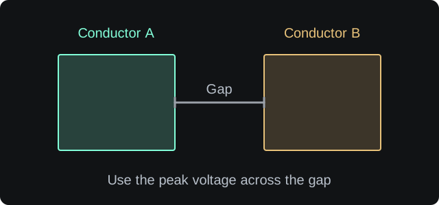
Conductor spacingTwo conductors separated by a minimum gap.gapconductorconductor
Input guide
Spacing between conductor edges

Measure the shortest distance between copper edges. The required spacing depends on the peak voltage and the construction category. Check the applicable product safety requirements separately.

Illustration only. Not to scale.

Minimum conductor spacing

N/A

MillimetresN/A
MilsN/A
MicrometresN/A
CategoryN/A
Method and assumptions

The table values are the minimum electrical clearances from the IPC-2221C conductor spacing table. Volts are peak DC or AC voltage between conductors.

  • 0–500 V uses the published table value for the selected construction category.
  • Above 500 V, the table's 301–500 V value is extended using the category slope.
  • This is a minimum electrical clearance, not a complete safety or creepage assessment.
  • Your PCB manufacturer, assembly process and applicable product standard may require more.

Use the peak voltage and round up the spacing

Select the construction that matches the real board: internal conductors, uncoated external conductors, solder-masked conductors, conformally coated conductors or component leads. Then use the peak voltage across the gap.

The result is a minimum table value. Round up to the nearest practical manufacturing grid and check the applicable product safety standard for creepage, clearance and altitude requirements.

What this does not model

  • Pollution degree, material group or comparative tracking index.
  • Creepage across the board surface, slots or cutouts.
  • Transient overvoltages, isolation barriers or regulatory testing.