Input guide
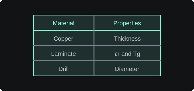
Look up typical copper, laminate and mechanical values. Use the manufacturer’s datasheet for the material or part you plan to use.
Illustration only. Not to scale.Copper weight
These are the values used by the current calculators.
| Base copper | Thickness |
|---|---|
| 0.25 oz | 0.35 mil |
| 0.5 oz | 0.70 mil |
| 1 oz | 1.40 mil |
| 1.5 oz | 2.10 mil |
| 2 oz | 2.80 mil |
| 2.5 oz | 3.50 mil |
| 3 oz | 4.20 mil |
| 4 oz | 5.60 mil |
| 5 oz | 7.00 mil |
Plating thickness
| Plating | Thickness |
|---|---|
| None | 0.00 mil |
| 0.5 oz | 0.70 mil |
| 1 oz | 1.40 mil |
| 1.5 oz | 2.10 mil |
| 2 oz | 2.80 mil |
| 2.5 oz | 3.50 mil |
| 3 oz | 4.20 mil |
Common laminate values
Typical values only. Use the laminate datasheet for controlled impedance work.
| Material | Er | Tg |
|---|---|---|
| FR-4, standard | 4.60 | 130 °C |
| FR-4, high Tg | 4.30 | 180 °C |
| Polyimide | 3.40 | 260 °C |
| PTFE | 2.10 | 260 °C |
| Ceramic-filled | 6.15 | N/A |
Mechanical information
Input guide
Check the wire, drill and fastener dimensions against the datasheet before committing to a footprint.
Illustration only. Not to scale.Typical reference values. Check the actual wire, drill and fastener datasheets for production work.
Copper wire gauge
| AWG | Diameter | Resistance |
|---|---|---|
| 10 | 2.588 mm | 1.00 Ω / 1000 ft |
| 12 | 2.053 mm | 1.59 Ω / 1000 ft |
| 14 | 1.628 mm | 2.53 Ω / 1000 ft |
| 16 | 1.291 mm | 4.02 Ω / 1000 ft |
| 18 | 1.024 mm | 6.39 Ω / 1000 ft |
| 20 | 0.812 mm | 10.15 Ω / 1000 ft |
| 22 | 0.644 mm | 16.14 Ω / 1000 ft |
| 24 | 0.511 mm | 25.67 Ω / 1000 ft |
| 26 | 0.405 mm | 40.81 Ω / 1000 ft |
| 28 | 0.321 mm | 64.90 Ω / 1000 ft |
| 30 | 0.255 mm | 103.20 Ω / 1000 ft |
Drill sizes
| Size | Inches | Millimetres |
|---|---|---|
| #60 | 0.040 in | 1.016 mm |
| #55 | 0.052 in | 1.321 mm |
| #50 | 0.070 in | 1.778 mm |
| #45 | 0.082 in | 2.083 mm |
| #40 | 0.098 in | 2.489 mm |
| #35 | 0.110 in | 2.794 mm |
| #30 | 0.128 in | 3.251 mm |
| 1/8" | 0.125 in | 3.175 mm |
| 3/16" | 0.188 in | 4.775 mm |
| 1/4" | 0.250 in | 6.350 mm |
Metric screw threads
| Size | Major diameter |
|---|---|
| M2 × 0.4 | 2.00 mm |
| M2.5 × 0.45 | 2.50 mm |
| M3 × 0.5 | 3.00 mm |
| M4 × 0.7 | 4.00 mm |
| M5 × 0.8 | 5.00 mm |
| M6 × 1.0 | 6.00 mm |
| M8 × 1.25 | 8.00 mm |