Calculate characteristic impedance and the derived transmission-line properties for common PCB cross-sections.
Manufacturer stack-up referenceJLCPCB and PCBWay
Choose a board, check its layers, then apply the values you need. Two-layer presets use an estimated core thickness. Your browser remembers the selected board and signal layer.
If no value is shown, enter the dielectric constant agreed with your PCB manufacturer. These impedance models use a single value for Er.
Includes common two-layer FR-4 presets from 0.4 to 2 mm with 1 or 2 oz copper, 298 PCBWay constructions with 4 to 18 layers, and 36 JLCPCB 1.6 mm constructions with 4 or 6 layers. The JLCPCB multilayer entries use 1 oz outer copper and 0.5 oz inner copper. For other JLCPCB options, see the manufacturer’s calculator. Confirm the construction for your order. The calculations do not include solder mask or manufacturing corrections.
Result
Enter your values to calculate a result.
Microstrip geometry
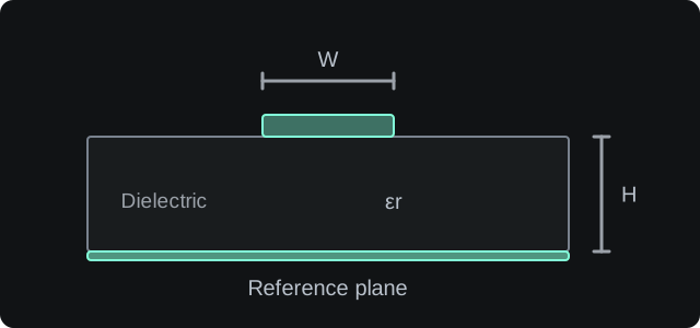
In this microstrip example, W is the trace width and H is the dielectric height above the reference plane. The dielectric constant and copper thickness also affect impedance. Other topologies use different geometry.
Illustration only. Not to scale.
Characteristic impedance
N/A
Effective ErN/A
Propagation delayN/A
Inductance per lengthN/A
Capacitance per lengthN/A
Method and assumptions
Microstrip uses the Hammerstad–Jensen quasi-static model with conductor-thickness correction and Kirschning–Jansen dispersion. Stripline uses the Cohn conformal-mapping solution with the Wadell thickness correction. Embedded microstrip uses the Wadell cover-filling model. Dual stripline uses the IPC-2251 dual-stripline expression. Coplanar waveguide uses the conductor-backed Ghione–Naldi model.
The formula selector offers the default model, the simplified IPC-2141 expression, or the Wadell/Wheeler effective-width form for microstrip and stripline.
Microstrip dispersion is valid for Er ≤ 20 and H/λ₀ ≤ 0.13.
Stripline, dual-stripline and coplanar results are quasi-static.
These models assume ideal transmission lines. They do not include copper roughness, solder mask or a limited ground-plane width.
Find a width or gap, then check tolerances
Uses the topology, geometry and formula selected above. Change one dimension while keeping the others fixed.
Search limits are always in millimetres. The solution is applied in the calculator’s selected units. Set limits that your PCB manufacturer can produce.
Manufacturing tolerance analysis
Enter ± tolerances around the current values. These are your assumptions, not limits supplied by the selected manufacturer.
Checks every combination of low, nominal and high values for the selected parameters. This is a sensitivity estimate, not a guaranteed production limit. Height variation scales both reference-plane distances and any dielectric cover together. Gap tolerance applies only to a differential pair or coplanar line.
How geometry and material affect impedance
Wider traces lower impedance. More dielectric height raises it. Higher Er lowers impedance and slows propagation. Use the PCB manufacturer’s layer stack for controlled-impedance design.
What this does not model
Solder mask, surface finish, copper roughness or finite ground-plane width.
Connectors, vias or discontinuities along the line.
Full-wave dispersion beyond the stated model limits.