SDG Electronics

Via stubs and differential vias

Estimate differential via impedance and the stub length at which quarter-wave resonance becomes a problem.

Inputs

Results update as you change the inputs.

Via pair
mm
mm
mm
mm
Stub
mm
ratio
%
GBaud

Result

Enter your values to calculate a result.

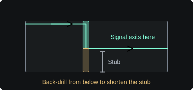
The unused section of a via

A signal can leave the via on an inner layer, leaving an unused barrel below it. This stub can resonate. Back-drilling removes part of the unused section.

Illustration only. Not to scale.

Differential via impedance

N/A

Odd-mode impedanceN/A
Effective dielectric constantN/A
Stub resonanceN/A
Maximum stub lengthN/A
Back-drill depthN/A
Nyquist frequencyN/A
Method and assumptions

Effective permittivity uses Er_eff = Er × (1 + anisotropy/200). The differential via impedance is an approximate via-pair estimate from the drill, reference-plane opening, spacing and height.

The stub quarter-wave resonance is f = c / (4L√Er_eff). The maximum stub length for the selected baud rate uses the Nyquist frequency f = baud/2.

  • This is an approximate model, not a 3D field solution.
  • Back-drill depth is the amount by which the stub exceeds the quarter-wave limit.
  • Check the actual stack-up, via registration and PCB manufacturer’s back-drilling limits.
Check via stubs at high baud rates

A via stub behaves like an open-circuited transmission line. When its length approaches a quarter wavelength at the signal’s Nyquist frequency, it creates a resonance notch. Back-drilling removes the unused portion of the barrel.